
|
|
||


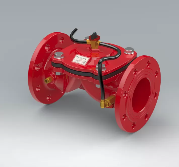
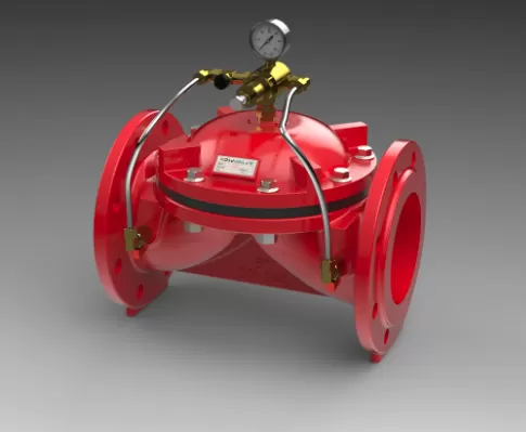
Hydraulic Control Valves These are automatic valves with direct diaphragm closure operating with line pressure from a controller. They are used to completely stop or give way to the flow, to turn it in other directions, to collect it from other directions, to control it between the minimum and maximum flow value.
PIV Hydraulic Control Valves are used in many areas such as agricultural irrigation, mains water lines, filtration systems and industrial facilities.
Properties
- Hydraulic Control valves operate completely automatically without the need for any extra energy.
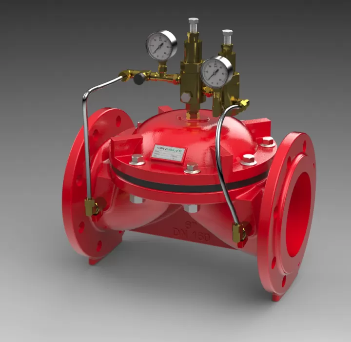
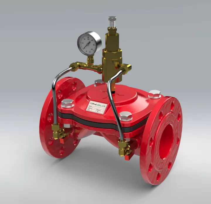
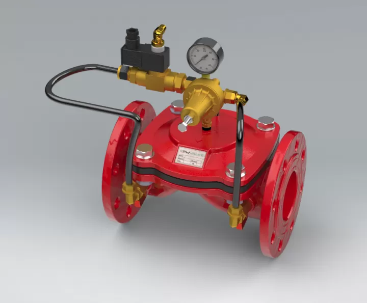
- Thanks to the 2-way pressure reducing pilot on the valve, the valve can reduce the output pressure to the desired value without being affected by flow changes.
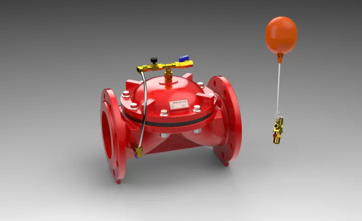
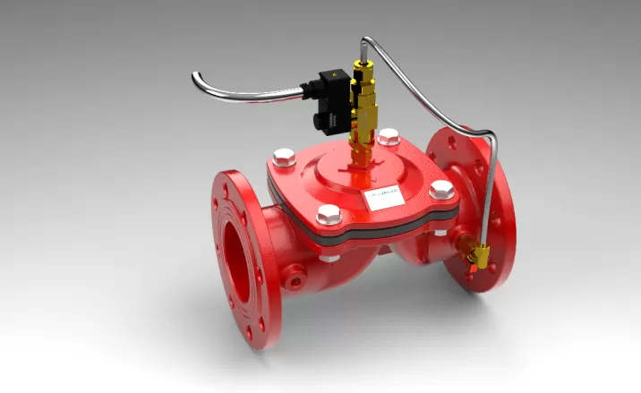
- It can be used with three different modes as open, closed and modulation.
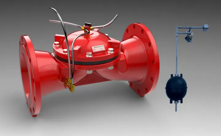
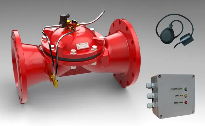
- It can turn itself off automatically when there is no water in the mains.
Working Principles

Valve Closing Mode
When the water pressure of the bidirectional pressure reducing pilots on the hydraulic control valve reaches above the diaphragm, the water creates a hydraulic force. Thanks to this pressure force, the diaphragm of the valve is pushed with the help of the spring force, closing the valve and sealing it.

Valve Opening Mode
When the pilots on the closed hydraulic control valve are brought to the discharge position, the pressure water on the diaphragm of the valve is discharged by opening the discharge port completely. When the line pressure of the valve is in a position to overcome the spring force, the water applies hydraulic force to the diaphragm, bringing the valve to the fully open position.

Modulation Mode
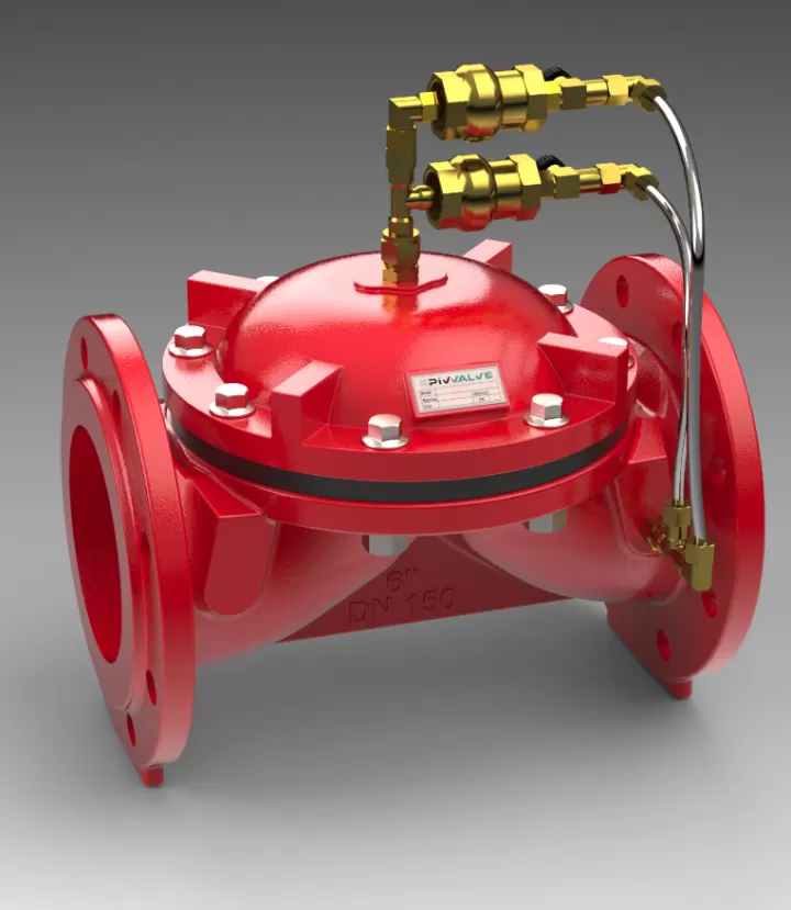
It is the pilot valves connected to the actuator mounted on the main valve, enabling the main valve to operate in Modulation Mode. It ensures that the main valve operates in modulation mode by continuously controlling the pressure of the fluid on the control chamber according to the flow amount and pressure to be adjusted.
| FLANGED | Connection | Material | Body | Operating pressure | ||||
| FLANGED | GGG40 | GLOBE | PN10-PN16-PN25 | |||||
| AVAILABLE DIAMETER | ||||||||
| mm | 80 | 100 | 125 | 150 | 200 | |||
| inch | 3 | 4 | 5 | 6 | 8 | |||
| GEAR | Connection | Material | Body | Operating pressure | ||||
| GEAR | GGG40 | GLOBE | PN10-PN16-PN25 | |||||
| AVAILABLE DIAMETER | ||||||||
| mm | 50 | 65 | ||||||
| inch | 2 | 2½ | ||||||

| FLANGED | DN | D | L | H | Weight | |||||
| inch | mm | inch | mm | inch | mm | inch | mm | lbs | kg | |
| 3 | 80 | 7,79 | 198 | 11,02 | 280 | 6,88 | 175 | 32,95 | 14,95 | |
| 4 | 100 | 8,66 | 220 | 13,18 | 335 | 7,08 | 180 | 42,43 | 19,92 | |
| 5 | 125 | 9,96 | 253 | 11,73 | 298 | 8,46 | 215 | * | * | |
| 6 | 150 | 11,33 | 288 | 15,59 | 396 | 12,91 | 328 | 103,61 | 47,8 | |
| 8 | 200 | * | * | * | * | * | * | * | * | |

| GEAR | DN | D | L | H | Ağırlık | |||||
| inch | mm | inch | mm | inch | mm | inch | mm | lbs | kg | |
| 2 | 50 | 1,45 | 37 | 7,12 | 181 | 3,09 | 78,5 | 7 | 3177 | |
| 2½ | 65 | 1,67 | 42,5 | 7,81 | 198,5 | 3,54 | 90 | 8,39 | 3808 | |
|
|||||||||||||||||||||||||||||||||||||||||||||||||||||||||||||||||||||||||||||||||||||||||||||||||||||||||||||||||||||||||||||||||


FLANŞLI
|
|
|
||||||||||||||||||||||||||||

DİŞLİ
|
|
|
||||||||||||||||||||||||||||
Meet the Pivvalve Power!
To subscribe to our newsletter, write your e-mail address in the section above and press the send button.
All rights reserved
Pivvalve