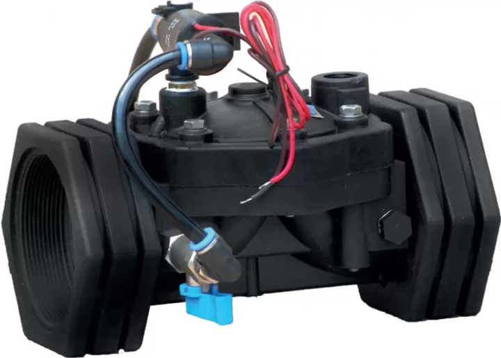
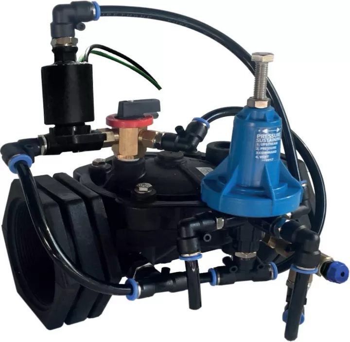
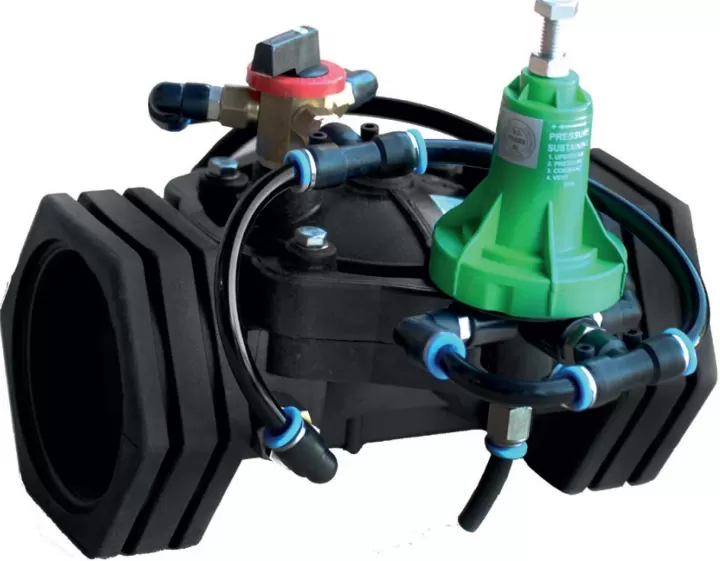
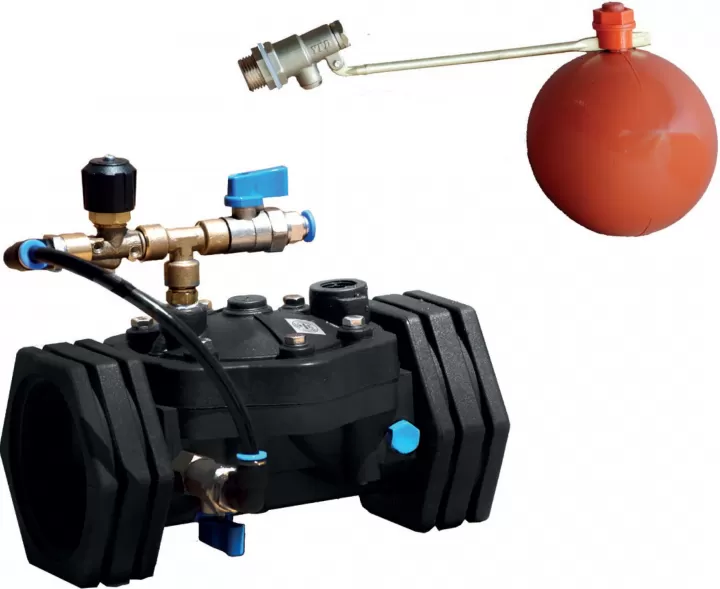

PIVVALVE Plastic Hydraulic Valves are automatic control valves with diaphragm working with line pressure. Hydraulic Control Valves are used in agricultural irrigation, drinking water lines, fıltration and industrial areas. PIVVALVE Plastic Valves are automatic control valves with diaphragm closure working with line pressure. Valve body and diaphragm design ensure smooth flow with minimum pressure loss. Since there is no bearing, bush and shaft in the valve body, valve life is longer. The only moving part of the valve is the diaphragm. PIVVALVE Plastic Hydraulic Control Valves are used in agricultural irrigation, drinking water lines, filtration andindustrial areas.
Features
• Easy operation and maintenance with simple structure
• Lower costs
• Wide pressure range operation
• Perfect modulation even at low flow rates
• Flexible diaphragm to open and close without impact
• Fully sealed with reinforced diaphragm and internal springu
• Wide range of control applications with different pilot valves
• Ability to work in horizontal and vertical positions in application areas
  |
 |
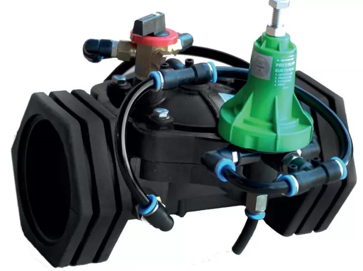
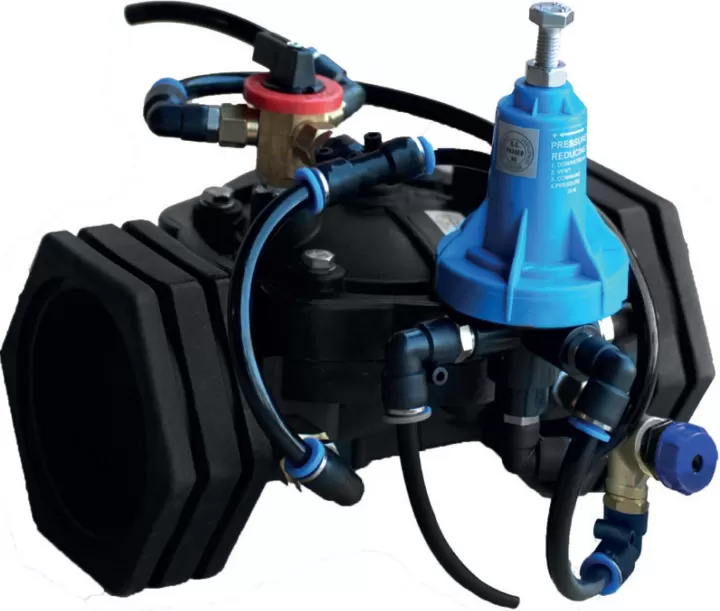
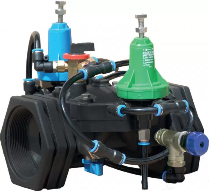
it is a fully automatic hydraulic control valve designed to perform the hydraulically desired modulation processes with the line pressure without the need far different energy sources such as electricity, pneumatic or mechanical in the main valve mains line.

Valve Closing Mode
Pilot valves connected to the main valve create a hydraulic force on the valve diaphragm when the water pressure at the valve inlet reaches the actuator actuator (control reservoir) of the valve. This hydraulic force that is created combines the diaphragm of the valve with the extra force exerted by the internal spring to ensure a tight seal.

Valve Opening Mode
When the path of the pilot valve on the main valve in the closed position is set to the discharge position, the pressurized water in the control chamber on the diaphragm of the main valve is discharged. When the line pressure reaches the spring force, the valve diaphragm applies a hydraulic force to the diaphragm to bring the valve into the full open position.

Modulation Mode
The pilot valves that connect the actuator to the main valve allow the main valve to operate in the modulated position. The va ive in the actuator of the main va ive ( control reservoir), according to the flow quantity or pressure conditions to be adjusted, ensures that the fluid continuously operates in the modulated position by controlling the pressure.

|
MAIN PARTS
|
|||||||||||||||||||||||||||||||||||||||||||||||
Basınç Kaybı Tablosu

MODEL
| Connection | Threaded | ||||
| Material | Glass Reinforced Polyamide | ||||
| Body | Globe | ||||
| Available Diameters | |||||
| inch | mm | ||||
| ¾ | 25 | ||||
| 1 | 32 | ||||
| 1½ | 40 | ||||
| 2 | 50 | ||||
| 2½ | 65 | ||||
| 3R | 80 | ||||
| Max. Operating Pressure | 10 Bar | ||||
HYDRAULIC PERFORMANCE
| inch | mm | inch | mm | inch | mm | inch | mm | inch | mm | inch | mm | |
| Valve Diameter | ¾ | 25 | 1 | 32 | 1½ | 40 | 2 | 50 | 2½ | 65 | 3R | 80 |
| Kv m3/h@1 bar | 50 | 55 | 60 | 70 | 80 | 90 | ||||||
| Cvgmp@1psi | 56 | 66 | 69 | 81 | 92 | 104 | ||||||

Kv : Valve Flow Coefficient ( 1 Bar Basınç Kaybında Geçen Debi M3/h @ 1 Bar)
Cv : Valve Flow Coefficient ( 1 Psi Basınç Kaybında Geçen Debi Gpm @ 1 Psi)
Q : Flow(m3/h, gpm)
Cv=1,155Kv 4P: Pressure Loss (Bar, psi) G:Specifıc gravity ofwater (far water =1,0)
 |
|
|||||||||||||||||||||||||||||||||||||||||||||||||||||||||||||||||||||||||||||||||||||||||||||||||

|
MAIN PARTS
|
|||||||||||||||||||||||||||||||||||||||||||||||||||||||||
Basınç Kaybı Tablosu

Model
| Connection | Flanged - Threaded | |||||||
| Material |
|
|||||||
| Body | Globe | |||||||
| Available Diameters | inch | mm | ||||||
| 3 | 80 | |||||||
| 4 | 100 | |||||||
| 6 | 150 | |||||||
| Max. Operating Pressure | 10 Bar | |||||||
Hidrolik Performans
| inch | mm | inch | mm | inch | mm | |
| Vana Çapı | 3 | 80 | 4 | 100 | 6 | 150 |
| Kv m3/h@1 bar | 166 | 208 | 220 | |||
| Cvgmp@1psi | 193 | 242 | 260 | |||

Kv : Vana Akış Katsayısı (1 Bar Basınç Basınç Kaybında Kaybında Geçen Debi m3/h @ 1 Bar)
Cv : Vana Akış Katsayısı (1 Bar Basınç Basınç Kaybında Kaybında Geçen Debi Gpm @ 1 Psi)
Q : Debi (m /h, gpm)
Cv= 1, 155Kv 4P: Basınç Kaybı (Bar, psi) G: Suyun Özgül Ağırlığı (Su= 1,0)

Boyut ve Ağırlıklar
| DN | D | L | H | Ağırlık | |||||||
| inch | mm | inch | mm | inch | mm | inch | mm | lbs | kg | ||
| 3 | 80 | 7,87 | 200 | 14,57 | 370 | 8,66 | 220 | 14,52 | 6,6 | ||
| 4 | 100 | 9 | 227 | 14,57 | 370 | 9,17 | 233 | 16,28 | 7,40 | ||
| 6 | 150 | 11,02 | 280 | 15,55 | 395 | 10,43 | 265 | 16,76 | 7,6 | ||
| DN | D | L | H | Ağırlık | |||||||
| inch | mm | inch | mm | inch | mm | inch | mm | lbs | kg | ||
| 3 | 80 | 4,72 | 120 | 11,58 | 294 | 7,05 | 179 | 10,25 | 4,65 | ||
| 4 | 100 | 4,72 | 120 | 13,23 | 336 | 7,28 | 185 | 9,7 | 4,4 | ||

|
|||||||||||||||||||||||||||||||||||||||||||||||
Debi - Basınç Kaybı Grafiği

Model
| Bağlantı | Dişli | ||||
| Malzeme | Cam Elyaf Takviyeli Poliamid | ||||
| Gövde | Açılı | ||||
| Mevcut Çapları | inch | mm | |||
| 2 | 50 | ||||
| 2½ | 65 | ||||
| 3R | 80 | ||||
| Maksimum İşletme Basıncı |
10 Bar | ||||
Hidrolik Performans
| inch | mm | inch | mm | inch | mm | |
| Vana Çapı | 2 | 50 | 2½ | 65 | 3R | 80 |
| Kv m3/h@1 bar | 51 | 56 | 66 | |||
| Cvgmp@1psi | 58,9 | 64,7 | 76,2 | |||
Kv : Vana Akış Katsayısı (1 Bar Basınç Basınç Kaybında Kaybında Geçen Debi m3/h @ 1 Bar)
Cv : Vana Akış Katsayısı (1 Bar Basınç Basınç Kaybında Kaybında Geçen Debi Gpm @ 1 Psi)
Q : Debi (m /h, gpm)
Cv= 1, 155Kv 4P: Basınç Kaybı (Bar, psi) G: Suyun Özgül Ağırlığı (Su= 1,0)

| DN | D | L | H | Ağırlık | |||||||
| inch | mm | inch | mm | inch | mm | inch | mm | lbs | kg | ||
| 2 | 50 | 3,4 | 86 | 8 | 203 | 6,77 | 172 | 2,86 | 1,3 | ||
| 2½ | 65 | 3,4 | 86 | 8 | 203 | 6,77 | 172 | 2,86 | 1,2 | ||
| 3R | 80 | 3,4 | 86 | 8 | 203 | 6,77 | 172 | 2,86 | 1,06 | ||

|
Ana Parçalar
|
|||||||||||||||||||||||||||||||||||||||||||||||||||||||||
Model
| Bağlantı | Flanşlı - Dişli | ||||
| Malzeme | Cam Elyaf Takviyeli Poliamid | ||||
| Gövde | Açılı | ||||
| Mevcut Çapları | inch | mm | |||
| 3 | 80 | ||||
| 4 | 100 | ||||
| 6 | 150 | ||||
| Maksimum İşletme Basıncı |
10 Bar | ||||
Kv : Vana Akış Katsayısı (1 Bar Basınç Basınç Kaybında Kaybında Geçen Debi m3/h @ 1 Bar)
Cv : Vana Akış Katsayısı (1 Bar Basınç Basınç Kaybında Kaybında Geçen Debi Gpm @ 1 Psi)
Q : Debi (m /h, gpm)
Cv= 1, 155Kv 4P: Basınç Kaybı (Bar, psi) G: Suyun Özgül Ağırlığı (Su= 1,0)

|
||||||||||||||||||||||||||||||||||||||||||||||||||||||||||||||||||||||||||||||||||||||||||||||||||||||||||||||
Meet the Pivvalve Power!
To subscribe to our newsletter, write your e-mail address in the section above and press the send button.
All rights reserved
Pivvalve